

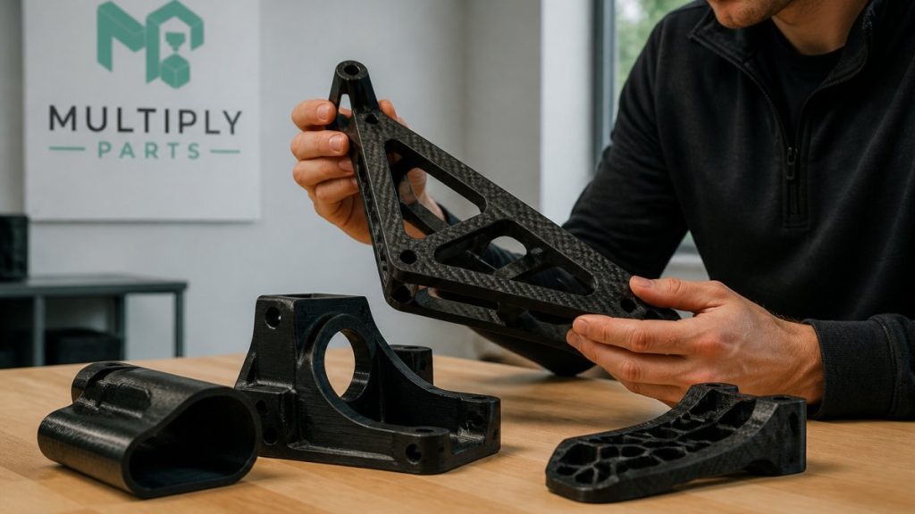
Benefits of Carbon Fiber Reinforced 3D Printing
Table of Contents
- Why Carbon Fiber 3D Printing Changes Part Performance
- Chopped Carbon Fiber vs Continuous Carbon Fiber
- How Strong Is Carbon Fiber PLA?
- Pros and Cons of Carbon Fiber Filament
- Carbon Fiber 3D Printing Applications Across Industries
- Anisotropy, Layer Adhesion, and Failure Modes
- Frequently Asked Questions
Last Updated: October 9, 2026
Why Carbon Fiber 3D Printing Changes Part Performance
The benefits of carbon fiber reinforced 3D printing start with how it works: carbon fiber is added to a thermoplastic base polymer so printed parts gain stiffness, strength, and dimensional stability that plain plastic cannot match. At MultiplyParts, we use these materials for sports equipment and EV components: a bracket that flexes in nylon comes out rigid and light in a carbon-fiber-reinforced filament.
The benefits of carbon fiber reinforced 3D printing come down to what happens inside the material: chopped or continuous fibers carry load, the polymer holds the shape, and the part behaves like a composite rather than plastic. That shift matters for functional parts, not display models.
Below, we break down where reinforcement helps, where it does not, and how to choose a material for your application.
Chopped Carbon Fiber vs Continuous Carbon Fiber
Chopped and continuous carbon fiber are the two reinforcement methods in additive manufacturing, and they are not interchangeable. Chopped fiber filament mixes short fibers into the plastic before extrusion; continuous fiber reinforcement lays unbroken strands inside the part during printing.
Chopped Fiber Filament: Practical and Affordable
Chopped-fiber filament runs on standard FFF printers with a hardened nozzle. Short fibers improve stiffness and reduce warping without special hardware, and printability stays close to the base polymer, making this the practical choice for brackets, housings, and jigs. The trade-off: short fibers do not bridge across a part like a continuous strand, so tensile strength gains are moderate.
Continuous Fiber Reinforcement: Maximum Strength
Continuous fiber reinforcement delivers the highest strength-to-weight ratio because unbroken fibers run along the load path. The catch is hardware and workflow. Continuous systems need dedicated machines, and fiber orientation must match how the part will be loaded. Get that wrong and you pay for strength you never use.
| Feature | Chopped Fiber | Continuous Fiber |
|---|---|---|
| Hardware | Standard FFF printer | Dedicated system |
| Strength gain | Moderate | High |
| Printability | Easy | Complex |
| Best for | Brackets, housings | Load-bearing parts |
How Strong Is Carbon Fiber PLA?
Carbon fiber PLA is stiffer and more dimensionally stable than standard PLA, but not dramatically stronger in tension. The fibers raise stiffness and reduce warping; they do not turn PLA into an engineering-grade structural material. That distinction trips up many buyers, so precision matters here.
What the Fiber Actually Changes
Adding chopped carbon fiber to PLA raises the elastic modulus, resistance to bending, far more than ultimate tensile strength. A carbon-fiber PLA bracket feels noticeably more rigid than the same bracket in unfilled PLA, yet it can still snap at a similar load applied in tension across the layers.
The other change is dimensional: carbon fiber has a much lower coefficient of thermal expansion than PLA, so the composite shrinks less as it cools.
Reading the Numbers in Context
Filament data sheets typically report tensile modulus, tensile strength, and sometimes flexural modulus for a molded specimen, not a printed one. Three caveats matter:
- Specimen type. Molded bars show the material’s ceiling. Printed bars show what your process delivers, and printed values are usually lower because layer bonds are the weak link.
- Orientation. A printed bar tested flat (load along the extrusion direction) will outperform the same bar tested on edge (load across the layers). The gap between those two numbers is the anisotropy of the part.
- Fiber loading. A 10% carbon-fiber PLA and a 20% carbon-fiber PLA are different materials. Higher loading usually means higher stiffness, lower elongation at break, and worse layer adhesion.
Treat any single “strength” figure as a starting point, not a specification. The honest comparison is carbon-fiber PLA versus the same base PLA printed on the same machine with the same orientation, not versus steel, aluminum, or a continuous-fiber composite.
Where Carbon Fiber PLA Fits
Carbon fiber PLA is excellent for prototypes, fixtures, jigs, and parts that hold shape under light load or resist warping on a large footprint.
For real load-bearing work, the polymer matters more than the fiber. Carbon-fiber-filled nylon or a continuous-fiber part outperforms carbon-fiber PLA in almost every structural scenario because the matrix is tougher and more heat-resistant. Choose the polymer for the environment, then add fiber for stiffness.
The most common mistake with carbon fiber PLA is treating the fiber as a strength upgrade. The fiber adds stiffness; the base polymer still sets the ceiling on impact, heat, and fatigue. If your part fails by snapping or by softening in service, more carbon fiber will not save it, a different matrix will.
A Quick Validation Workflow
Before committing a design to carbon fiber PLA, run three checks:
- Load direction. Identify the primary load path and confirm it runs along the layers, not across them.
- Temperature. Confirm the part’s service temperature stays comfortably below PLA’s softening range, with margin for radiant heat and direct sun.
- Failure mode. Decide whether the part should bend, crush, or snap, and whether a brittle fracture is acceptable. If it is not, move to a tougher matrix.
That sequence costs a design review and a test print, far cheaper than discovering the limits in the field.
Pros and Cons of Carbon Fiber Filament
The pros and cons of carbon fiber filament are best weighed against your specific part rather than in the abstract.
Pros:
- Higher stiffness and strength-to-weight ratio than unfilled plastic
- Better dimensional stability and less warping and shrinkage
- Lightweight parts suited to sports and EV applications
Cons:
- Abrasive filament wears standard brass nozzles, so a hardened nozzle is required
- Higher print temperature and slower speeds than plain filament
- Reduced layer adhesion when fiber content rises, which affects anisotropy
The hardness cuts both ways: it is why these parts last, and why your nozzle and extruder must be set up for abrasive material before you start.
Carbon Fiber 3D Printing Applications Across Industries
Carbon fiber 3D printing applications cluster where low weight and high stiffness matter more than raw tensile strength. Reinforcement earns its cost when a part has a defined load path, a weight constraint, and a need for dimensional stability; without those, plain polymer is the smarter buy. Engineers must carefully weigh these performance trade-offs when selecting materials for 3D printing to ensure that the final geometry provides the necessary ballistic protection.
Matching the Matrix to the Environment
The fiber gets the attention, but the base polymer decides whether a part survives. The same chopped carbon fiber can be compounded into very different matrices, each trading off temperature, chemical resistance, moisture uptake, impact toughness, and outdoor durability. A part that performs in a climate-controlled lab can fail outdoors, in a chemical wash-down, or under repeated impact, not because the fiber was wrong, but because the matrix was.
A useful way to think about it is to pick the matrix first, then add fiber for stiffness:
- PLA-based composites are the easiest to print and the most dimensionally stable, but they soften at low temperatures and are brittle under impact. Best for indoor fixtures, prototypes, and visual parts that see light load.
- PETG-based composites add toughness and moderate heat resistance while staying easy to print. A reasonable middle ground for brackets, enclosures, and parts exposed to occasional bumps.
- Nylon (PA) composites are the workhorse for functional parts: high toughness, good fatigue resistance, and the best strength-to-weight among common FFF matrices. The trade-off is moisture uptake, nylon absorbs water from the air, which changes dimensions and print behavior, so drying and storage discipline are mandatory.
Application-Led Selection in Practice
The fastest way to choose is to work backward from the environment, not forward from the material.
- Define the service temperature. Add margin for radiant heat, direct sun, and nearby motors. If the part will sit in a hot vehicle interior or near an exhaust, commodity PLA is out regardless of fiber content.
- Define the chemical exposure. Fuels, oils, solvents, and cleaning agents all attack different polymers differently. Nylon and PETG handle many oils well; PLA does not.
- Define the moisture and UV exposure. Outdoor parts favor ASA or a stabilized nylon. Indoor parts rarely justify the extra cost.
- Define the impact and fatigue profile. Repeated vibration and shock favor nylon; single-event stiffness favors a stiffer, more brittle composite.
- Define the load path. Confirm the primary stress runs along the layers, and orient the print accordingly.
Run those five questions and the shortlist usually collapses to one or two materials.
Where These Parts Win
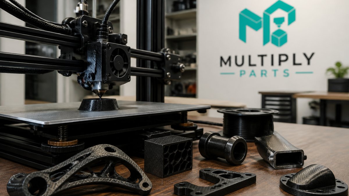
In the sports and EV markets, the pattern repeats: brackets, mounts, housings, and custom or replacement parts that need to be light, rigid, and repeatable. MultiplyParts specializes in exactly these categories, sports equipment components and electric vehicle accessories, with no minimum order quantity and fast turnaround. HitchStyle.com is one example. For prototyping a new invention or scaling an established brand, the same material properties that win on the bench carry through to end-use parts.
Where They Do Not
Carbon fiber reinforcement is the wrong tool when the part is decorative, the load is undefined, the service environment exceeds the matrix’s limits, or the part is small enough that stiffness was never the constraint. In those cases the fiber adds cost, wears nozzles faster, and can reduce layer adhesion without delivering a usable benefit. Knowing when to say no is as valuable as knowing which fiber to specify.
Pick the polymer for the environment, then add fiber for stiffness. The fiber is a modifier, not a substitute for choosing the right matrix, and the application, not the data sheet, decides which matrix is right.
Anisotropy, Layer Adhesion, and Failure Modes
Anisotropy is the tendency of a printed part to be stronger along the layer lines than across them, and it is the biggest reason carbon-fiber parts fail unexpectedly.
A part can pass a bench test and still fail in service if the load runs across the layers. Three failure modes show up again and again:
- Delamination: layers separate when the load pulls across the bond, common with high fiber content and cool print temperatures.
- Brittle fracture: stiff, fiber-filled parts snap instead of bending, so impact loads concentrate at edges and corners.
- Fiber misalignment: fibers run the wrong way relative to the load, so the reinforcement does nothing where it is needed.
Print temperature, build orientation, and part design all influence these outcomes. Aligning the load path with the fiber direction is the highest-use fix, costing nothing but a design review.
Strength data on a filament label tells you how the material behaves in a perfect orientation. Real parts fail at the weakest interface, so design for the load direction and test the actual geometry.
Choosing the right reinforced material is the difference between a part that performs and one that fails in the field. Get an Instant Quote and turn your design into a professionally manufactured reality.
Frequently Asked Questions
Is carbon fiber PLA actually stronger than regular PLA?
Carbon fiber PLA shows higher stiffness and dimensional stability than standard PLA, but tensile strength gains are modest. The short fibers improve rigidity and reduce warping, which matters for functional parts that need to hold shape under load. For applications requiring maximum strength, continuous fiber reinforcement or materials like carbon fiber nylon deliver better results. Carbon fiber PLA works well for brackets, housings, and prototypes where stiffness and printability matter more than ultimate tensile strength.
What is the difference between chopped and continuous carbon fiber 3D printing?
Chopped carbon fiber filament mixes short fibers into a thermoplastic base polymer like PLA, PETG, or nylon. These print on standard FDM machines with a hardened nozzle. Continuous carbon fiber reinforcement embeds unbroken strands during the print, creating parts with significantly higher tensile and flexural strength. Chopped fiber is easier to print and more affordable. Continuous fiber requires specialized equipment but produces parts closer to aluminum performance for load-bearing applications.
Which applications benefit most from carbon fiber reinforced 3D printing?
Carbon fiber reinforced parts excel in applications needing high strength-to-weight ratio: EV brackets, drone frames, sports equipment components, robotic arms, and custom automotive parts. The material also suits jigs, fixtures, and tooling where dimensional stability under heat matters. Prototyping functional parts that will eventually be machined or molded benefits from carbon fiber because it approximates final material properties more closely than standard filaments, reducing surprises during production.
What are the main disadvantages of carbon fiber filament?
Carbon fiber filament wears out brass nozzles quickly, so a hardened steel or ruby nozzle is necessary. The material costs more than standard PLA or PETG. Layer adhesion can be weaker than unfilled filaments because fibers interfere with bonding between layers. Parts are also abrasive and may require slower print speeds. Post-processing is harder since sanding carbon fiber composites exposes fibers that need respiratory protection. These trade-offs are manageable when the application justifies the performance gains.
